Permittivity and Permeability of Materials Obstacle Course: Difference between revisions
| Line 37: | Line 37: | ||
=== * A Better Permittivity-Capacitance Measurement of a ''Lossless'' Material === | === * A Better Permittivity-Capacitance Measurement of a ''Lossless'' Material === | ||
coming soon... | |||
[[File:Epsiloncap2.png |right |350px]] | [[File:Epsiloncap2.png |right |350px]] | ||
| Line 59: | Line 61: | ||
## Do the above procedure for at least three frequencies between 10 MHz and 50 MHz. | ## Do the above procedure for at least three frequencies between 10 MHz and 50 MHz. | ||
## Plot <math>\epsilon'_r</math> and <math>\epsilon''_r</math> as a function of frequency. | ## Plot <math>\epsilon'_r</math> and <math>\epsilon''_r</math> as a function of frequency. | ||
=== Waveguide Techniques(above 50MHz) === | |||
coming soon... | |||
Revision as of 18:57, 21 May 2018
PAGE UNDER CONSTRUCTION
Permanent Materials
- 6061 3/8" Al rod stock
- Teflon
- Glass microscope slide
- HP Signal Generator (DC-1 GHz)
- Oscilloscope (at least 1GHz bandwidth)
- Miscellaneous electrical components
Materials to Borrow When Necessary
- Milling machine
- Lathe
Activities
Reading
- Read the Wikipedia articles on permittivity and permeability. With the help of the instructor or TA try to achieve a physical understanding of just what the permittivity and permeability mean in a bulk material.
- Read the first three sections of this paper (pages 1-27). Pay particular attention to the permittivity () / capacitance and permeability () / inductance associations.
Capacitance Techniques (Below 10MHz)
* Permittivity of a Lossless Material From a Capacitance Measurement

- Place three samples (air, Teflon, glass) between the aligned and polished ends of two 3/8" diameter, 1/2" lengths of 6061 Al rods (as shown at right). should be on the order of 1 mm. Measure the capacitances and, from the known surface area and spacing , determine the material's relative permittivity. (for a capacitor with no fringing fields).
- How do your measured permittivity values compare to standard reference values?
- Use this web applet to build a capacitor and observe the field lines . Are there fringing fields?
Failed to parse (SVG (MathML can be enabled via browser plugin): Invalid response ("Math extension cannot connect to Restbase.") from server "https://wikimedia.org/api/rest_v1/":): {\displaystyle \epsilon_r}
(air): 1.000536
Failed to parse (SVG (MathML can be enabled via browser plugin): Invalid response ("Math extension cannot connect to Restbase.") from server "https://wikimedia.org/api/rest_v1/":): {\displaystyle \epsilon_r}
(Teflon): 2.1
Failed to parse (SVG (MathML can be enabled via browser plugin): Invalid response ("Math extension cannot connect to Restbase.") from server "https://wikimedia.org/api/rest_v1/":): {\displaystyle \epsilon_r}
(glass): 3.7-10
* A Better Permittivity-Capacitance Measurement of a Lossless Material
coming soon...

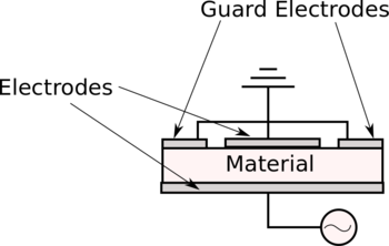
- Use this web applet to build a guarded-electrode capacitor (as shown at the right) and observe the field lines . Are there fringing fields?
- Measure the three permittivities (air, Teflon, glass) again using this guarded-electrode setup.
- How do these results compare to your first (unguarded) measurements?
- How do these results compare to the standard values?
The measurements above for a lossless material amount to requiring the permittivity to be real (as opposed to complex). However, for a lossy material, the permittivity is complex and we need an additional characteristic (beyond simply the capacitance) to characterize the material. This additional characteristic is the conductance Failed to parse (SVG (MathML can be enabled via browser plugin): Invalid response ("Math extension cannot connect to Restbase.") from server "https://wikimedia.org/api/rest_v1/":): {\displaystyle G}
. The measurement below will include the conductance of the material.
* Permittivity of a Lossy Material From a Capacitance Measurement (up to 50 MHz)

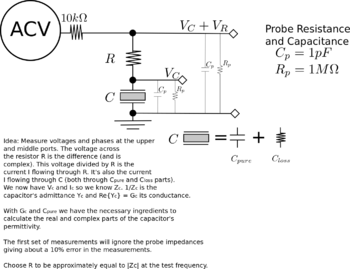
- Employ the guarded-electrode setup above and measure the lossy material's capacitance and conductance. Failed to parse (SVG (MathML can be enabled via browser plugin): Invalid response ("Math extension cannot connect to Restbase.") from server "https://wikimedia.org/api/rest_v1/":): {\displaystyle C=\epsilon^'\frac{A}{d}}
and Failed to parse (SVG (MathML can be enabled via browser plugin): Invalid response ("Math extension cannot connect to Restbase.") from server "https://wikimedia.org/api/rest_v1/":): {\displaystyle G=\omega \epsilon^{''} \frac{A}{d}}
, where Failed to parse (SVG (MathML can be enabled via browser plugin): Invalid response ("Math extension cannot connect to Restbase.") from server "https://wikimedia.org/api/rest_v1/":): {\displaystyle \epsilon^'\text{/}}
Failed to parse (SVG (MathML can be enabled via browser plugin): Invalid response ("Math extension cannot connect to Restbase.") from server "https://wikimedia.org/api/rest_v1/":): {\displaystyle \epsilon^{''}}
are, respectively, the real and imaginary parts of the complex permittivity.
- Simultaneously measure the voltage across the resistor Failed to parse (SVG (MathML can be enabled via browser plugin): Invalid response ("Math extension cannot connect to Restbase.") from server "https://wikimedia.org/api/rest_v1/":): {\displaystyle V_R} and Lock-in voltage Failed to parse (SVG (MathML can be enabled via browser plugin): Invalid response ("Math extension cannot connect to Restbase.") from server "https://wikimedia.org/api/rest_v1/":): {\displaystyle V_{Lock-in}} at Failed to parse (SVG (MathML can be enabled via browser plugin): Invalid response ("Math extension cannot connect to Restbase.") from server "https://wikimedia.org/api/rest_v1/":): {\displaystyle V_{out}} . Employ a lock-in time constant that is much longer than the period of the AC driving voltage. The lock-in voltage Failed to parse (SVG (MathML can be enabled via browser plugin): Invalid response ("Math extension cannot connect to Restbase.") from server "https://wikimedia.org/api/rest_v1/":): {\displaystyle V_{Lock-in}} is given by Failed to parse (SVG (MathML can be enabled via browser plugin): Invalid response ("Math extension cannot connect to Restbase.") from server "https://wikimedia.org/api/rest_v1/":): {\displaystyle V_{Lock-in}=\frac{1}{2}V_{out} \,\, cos(\theta)} , where Failed to parse (SVG (MathML can be enabled via browser plugin): Invalid response ("Math extension cannot connect to Restbase.") from server "https://wikimedia.org/api/rest_v1/":): {\displaystyle V_{out}} is the voltage across the capacitor and Failed to parse (SVG (MathML can be enabled via browser plugin): Invalid response ("Math extension cannot connect to Restbase.") from server "https://wikimedia.org/api/rest_v1/":): {\displaystyle \theta} is the phase difference between the AC driving voltage and Failed to parse (SVG (MathML can be enabled via browser plugin): Invalid response ("Math extension cannot connect to Restbase.") from server "https://wikimedia.org/api/rest_v1/":): {\displaystyle V_{out}}
- The current through the capacitor is given by Failed to parse (SVG (MathML can be enabled via browser plugin): Invalid response ("Math extension cannot connect to Restbase.") from server "https://wikimedia.org/api/rest_v1/":): {\displaystyle I_C=V_R/R} . The voltage across the capacitor is given by Failed to parse (SVG (MathML can be enabled via browser plugin): Invalid response ("Math extension cannot connect to Restbase.") from server "https://wikimedia.org/api/rest_v1/":): {\displaystyle V_{out}=Z_C I_C} , where Failed to parse (SVG (MathML can be enabled via browser plugin): Invalid response ("Math extension cannot connect to Restbase.") from server "https://wikimedia.org/api/rest_v1/":): {\displaystyle Z_C} is the capacitor's impedance. Solve for the impedance Failed to parse (SVG (MathML can be enabled via browser plugin): Invalid response ("Math extension cannot connect to Restbase.") from server "https://wikimedia.org/api/rest_v1/":): {\displaystyle Z_C} .
- The capacitor's admittance Failed to parse (SVG (MathML can be enabled via browser plugin): Invalid response ("Math extension cannot connect to Restbase.") from server "https://wikimedia.org/api/rest_v1/":): {\displaystyle Y_C} is given by Failed to parse (SVG (MathML can be enabled via browser plugin): Invalid response ("Math extension cannot connect to Restbase.") from server "https://wikimedia.org/api/rest_v1/":): {\displaystyle Y_C=\frac{1}{Z_C}} , where the Failed to parse (SVG (MathML can be enabled via browser plugin): Invalid response ("Math extension cannot connect to Restbase.") from server "https://wikimedia.org/api/rest_v1/":): {\displaystyle Re(Y_C)=G} (the conductance) and the Failed to parse (SVG (MathML can be enabled via browser plugin): Invalid response ("Math extension cannot connect to Restbase.") from server "https://wikimedia.org/api/rest_v1/":): {\displaystyle Im(Y_C)=B} (the susceptance). Calculate Failed to parse (SVG (MathML can be enabled via browser plugin): Invalid response ("Math extension cannot connect to Restbase.") from server "https://wikimedia.org/api/rest_v1/":): {\displaystyle G} .
- Read section 13.1 (pages 106-107) in this [paper].
- Calculate the relative permittivity Failed to parse (SVG (MathML can be enabled via browser plugin): Invalid response ("Math extension cannot connect to Restbase.") from server "https://wikimedia.org/api/rest_v1/":): {\displaystyle \epsilon_r} as Failed to parse (SVG (MathML can be enabled via browser plugin): Invalid response ("Math extension cannot connect to Restbase.") from server "https://wikimedia.org/api/rest_v1/":): {\displaystyle \epsilon'_r=\frac{C}{C_{air}}} and Failed to parse (SVG (MathML can be enabled via browser plugin): Invalid response ("Math extension cannot connect to Restbase.") from server "https://wikimedia.org/api/rest_v1/":): {\displaystyle \epsilon''_r=\frac{G}{\omega C_{air}}} .
- Do the above procedure for at least three frequencies between 10 MHz and 50 MHz.
- Plot Failed to parse (SVG (MathML can be enabled via browser plugin): Invalid response ("Math extension cannot connect to Restbase.") from server "https://wikimedia.org/api/rest_v1/":): {\displaystyle \epsilon'_r} and Failed to parse (SVG (MathML can be enabled via browser plugin): Invalid response ("Math extension cannot connect to Restbase.") from server "https://wikimedia.org/api/rest_v1/":): {\displaystyle \epsilon''_r} as a function of frequency.
Waveguide Techniques(above 50MHz)
coming soon...


