Fiber-Optics Obstacle Course: Difference between revisions
Jump to navigation
Jump to search
| Line 40: | Line 40: | ||
## Break your patch cable in the middle and repair it with a fusion splice (see fusion splicer manual [[Media:X77_Fusion_Splicer.pdf| Fusion Splicer Manual]] and eBook.<br> | ## Break your patch cable in the middle and repair it with a fusion splice (see fusion splicer manual [[Media:X77_Fusion_Splicer.pdf| Fusion Splicer Manual]] and eBook.<br> | ||
## Measure the power loss through your fusion spliced patch cable.<br> | ## Measure the power loss through your fusion spliced patch cable.<br> | ||
## Break the fusion splice out of the patch cord leaving two partly-connectorized fibers. | ## Optional: Break the fusion splice out of the patch cord leaving two partly-connectorized fibers. Strip and cleave the unconnectorized end of one of the fibers and use the free-space-to-fiber coupler to couple a free space beam into the SM fiber (our coupler is not quite as that shown at the right).<br> | ||
# Verify that a fiber isolator exhibits low power loss in one direction only.<br> | # Verify that a fiber isolator exhibits low power loss in one direction only.<br> | ||
Optional: | |||
# Use in-fiber polarizer and fiber polarization controller to measure extinction ratio of in-fiber polarizer | # Use in-fiber polarizer and fiber polarization controller to measure extinction ratio of in-fiber polarizer | ||
# Use a source, MM fiber, the fiber mode scrambler, the free-space-to-fiber coupler and a video camera to observe the transverse modes of a MM fiber. | # Use a source, MM fiber, the fiber mode scrambler, the free-space-to-fiber coupler and a video camera to observe the transverse modes of a MM fiber.<br> | ||
# Construct an Erbium-Doped SM Fiber Ring Laser. Measure its optical power vs. pump current/power curve. | # Construct an Erbium-Doped SM Fiber Ring Laser. Measure its optical power vs. pump current/power curve. [http://hank.uoregon.edu/experiments/edfa-cwlaser/edfa-cwlaser.html| See here for more details] | ||
[http://hank.uoregon.edu/experiments/edfa-cwlaser/edfa-cwlaser.html| See here for more details] | |||
- Submit a write-up outlining your activities, results and the answers to any questions asked above. | |||
* '''CLEAN UP THE OBSTACLE COURSE SETUP AFTER USE''' | * '''CLEAN UP THE OBSTACLE COURSE SETUP AFTER USE''' | ||
Revision as of 23:41, 23 October 2015
- When working with bare fibers or lasers wear appropriate safety (or laser) goggles. If you're unsure about this please consult the instructor or lab TAs.
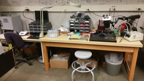
Permanent Materials (located at the fiber station):

- Bulk SMF
- Fiber connectors
- Polishing materials
- Free-space-to-fiber coupler
- Fiber chucks
- Fiber mode scrambler
- 50/50 fiber splitter/combiner
- 90/10 fiber splitter/combiner
- 1550/980nm WDM
- 1550nm fiber isolator
- 1550nm in-fiber polarizer
- fiber polarization controller
- 980nm pump laser
- Erbium-Doped fiber
Materials to borrow when necessary
- fiber power meter
- fusion splicer
- CLEAN UP THE OBSTACLE COURSE SETUP AFTER USE
Keep a journal of your activities, results and answers to any questions asked in the activities below. You will use this for your brief write-up.
Activities
- Read the first 4 chapters of John Crisp's eBook, "Introduction to Fiber Optics". Consult remaining chapters as needed.
- Look over the APL's Fiber Optics Wiki page Fiber Optics and links therein.
- Consulting Thorlab's Fiber Polishing Manual Fiber Polishing and Connectorization and the (above mentioned) eBook construct a 1 meter SM FC-APC to FC-APC fiber patch cable (you will find everything you need at the fiber polishing station).
Fiber Epoxy Mixing Instructions
Fiber Polishing Film Grades - color code/grit size- Measure power loss through your patch cable.

fiber coupler - Break your patch cable in the middle and repair it with a fusion splice (see fusion splicer manual Fusion Splicer Manual and eBook.
- Measure the power loss through your fusion spliced patch cable.
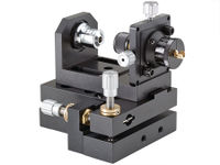
- Optional: Break the fusion splice out of the patch cord leaving two partly-connectorized fibers. Strip and cleave the unconnectorized end of one of the fibers and use the free-space-to-fiber coupler to couple a free space beam into the SM fiber (our coupler is not quite as that shown at the right).
- Measure power loss through your patch cable.
- Verify that a fiber isolator exhibits low power loss in one direction only.
Optional:
- Use in-fiber polarizer and fiber polarization controller to measure extinction ratio of in-fiber polarizer
- Use a source, MM fiber, the fiber mode scrambler, the free-space-to-fiber coupler and a video camera to observe the transverse modes of a MM fiber.
- Construct an Erbium-Doped SM Fiber Ring Laser. Measure its optical power vs. pump current/power curve. See here for more details
- Submit a write-up outlining your activities, results and the answers to any questions asked above.
- CLEAN UP THE OBSTACLE COURSE SETUP AFTER USE