Interferometers: Difference between revisions
No edit summary |
No edit summary |
||
| Line 24: | Line 24: | ||
[[Media:How_Does_a_Mach-Zehnder_Interferometer_Work?.pdf]] | [[Media:How_Does_a_Mach-Zehnder_Interferometer_Work?.pdf]] | ||
[http://www.phy.davidson.edu/stuhome/cabell_f/diffractionfinal/pages/michelson.htm| The Michelson Interferometer] | [http://www.phy.davidson.edu/stuhome/cabell_f/diffractionfinal/pages/michelson.htm | The Michelson Interferometer] | ||
Revision as of 18:36, 6 August 2014
The goal of the spectroscopy project was to create a Michelson, Mach-Zehnder and Sagnac Interferometer. Each setup utilized a 632.8nm Helium-Neon laser.
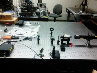
In order to reduce fringe-drift, the Michelson interferometer employed both an optical iris and an optical isolator. The setup of the Michelson interferometer is shown in Figure 1. The Michelson interferometer was used to measure both the "voltage-to-expansion" ratio of a PZT and the coherence length of the He-Ne laser.
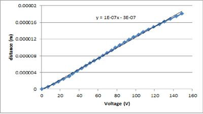
To measure the "voltage-to-expansion" ratio, the PZT was wedged in the track of he adjustable mirror. By increasing the voltage across the PZT and simultaneously counting the number of fringes that passed an arbitrary point on the projection screen, it was possible to measure the expansion distance of the PZT using the relation d=m*lambda/2. Multiple measurements were recorded and plotted in Figure 2. The slope of the graph indicates the expansion rate of the PZT is 100nm/Volt.
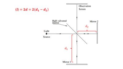
To measure the coherence length of the He-Ne laser, mirror 1 was gradually moved backwards until the interference pattern was no longer visible. The coherence length <l>, is given by the relation <l>=2*d, where d is the difference in length between the arms of the interferometer (Figure 3). The coherence length was determined to be 78cm.
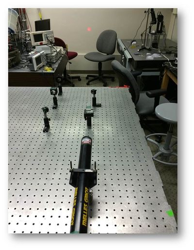
The mach-zehnder interferometer setup is shown in Figure 4. As with the Michelson interferometer, an optial iris was employed to minimize outside noise. However, the optical isolator proved unnecessary with the Mach-Zehnder interferometer as no fringe drift was observed.
The Setup of the Sagnac interferometer is shown in figure 5. To rotate the interferometer, it was placed on a stool. The power source and digital oscilloscope were placed on another platform above the interferometer (Figure 6).
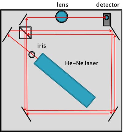

The intended goal with the Sagnac interferometer was to verify the wavelength of the He-Ne laser. This could be accomplished by the relations z=(4*omega*A)/(lambda*c) and P(t)=(Pin/2)(1+cos(z(t)). Here z is the phase-change, omega is the angular velocity of the rotating platform, A is the area enclosed the arms of the interferometer, and P(t) is the photocurrent.
Due to outside noise, it was not possible to obtain a clean measurement of the photocurrent. In order to reduce noise, future experiments might include a lock-in amplifier.