Vacuum-Component Assembly: Tips and Procedures: Difference between revisions
No edit summary |
No edit summary |
||
| Line 1: | Line 1: | ||
=Vacuum Components= | =UHV Vacuum Components= | ||
[[File:Conflat Flange.jpg|left|250px|CF Conflat Flange]][[File:KF 25 Tee.jpg|350px|QF/KF Quick Flange Tee]][[File:CF to KF.jpg|right|250px|CF to KF adapter]] | [[File:Conflat Flange.jpg|left|250px|CF Conflat Flange]][[File:KF 25 Tee.jpg|350px|QF/KF Quick Flange Tee]][[File:CF to KF.jpg|right|250px|CF to KF adapter]] | ||
| Line 39: | Line 39: | ||
[[File:6-way cross.png|center|250px|CF 6-way cross]] | [[File:6-way cross.png|center|250px|CF 6-way cross]] | ||
Example of assembled UHV system | |||
[[File:Uhv system.jpg|600px]] | |||
Revision as of 22:25, 8 April 2014
UHV Vacuum Components
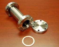
The flange on the left is called a CF or Conflat flange. Bolts, nuts and copper gaskets are used to attached components.
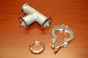
The flange in the middle is called a QF (or KF) Quick Flange. O-rings and clamps are used to attach components.
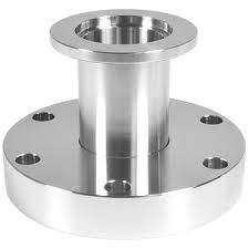
The rightmost component is a CF-to-KF adapter.
Making CF attachments
When making CF attachments bolts, nuts, washers and copper gaskets are used.

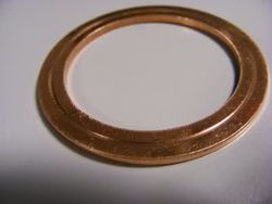
Observe the indented ring on the used copper gasket. It is caused by the CF flange knife edge and provides the UHV (Ultra High Vacuum) seal.
Clean all components in a mild detergent solution in the sonicator. Rinse the sonicated components in distilled water then methanol. Dry components with (e.g.) the heat gun. Inspect the CF knife edges for damage (see photos below). Damaged knife edges like those shown below will leak and limit vacuums to the mtorr-torr level.
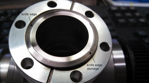
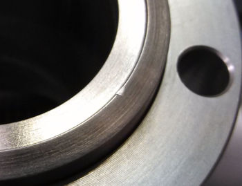
Align CF parts. Be careful not to bang parts together and damage the knife edges (easily done). Do not attempt to mate misaligned parts by just tightening the bolts.
Using clean gloves, place a (fresh/new) copper gasket against the knife edge seal of one of two standard CF flanges, preferably the flange most likely to hold and support the gasket from falling. With the gasket in place arrange mating flange with the desired bolt hole orientation. If flanges are fitted with leak-test grooves, these should be aligned. With flanges aligned, insert proper size bolt and hand tighten. Washers are typically used on the nut side of the fastener assembly. Repeat this procedure with the remaining bolts.
After hand tightening all bolts, support bolt and turn nut using two closed-end box wrenches. The tightening process must be done gradually in 1/8 to 1/4 turn increments in an alternating crisscross pattern. Continue this incremental tightening until the desired torque ratings have been achieved. Tightening bolts in this fashion will insure a reliable seal with even gasket compression and deformation.
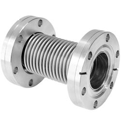
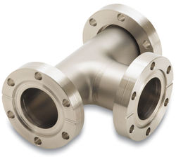
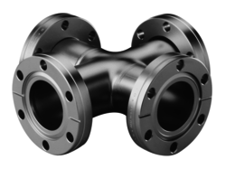
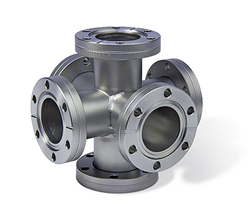
UHV component examples:
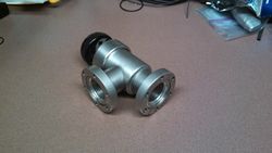
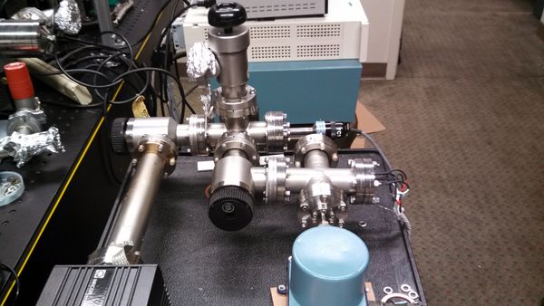
Example of assembled UHV system
