Digital-Electronics Obstacle Course: Difference between revisions
Jump to navigation
Jump to search
No edit summary |
No edit summary |
||
| Line 15: | Line 15: | ||
- inductance meter<br> | - inductance meter<br> | ||
- Keithley voltage supply | - Keithley voltage supply | ||
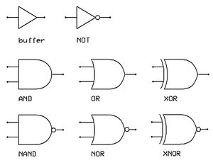
[[File:Gate_symbols.jpg|thumb|right|Digital Electronic Component Symbols| | [[File:Gate_symbols.jpg|thumb|right|Digital Electronic Component Symbols|300px]]<br><br><br><br><br><br><br> | ||
=== Activities === | === Activities === | ||
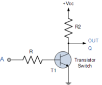
[[File:Traninverter.png|right|200px]] | |||
# Read chapter 8 of Horowitz & Hill's ''The Art of Electronics''. | # Read chapter 8 of Horowitz & Hill's ''The Art of Electronics''. | ||
# Read Chapters 10 and 11 of | # Read Chapters 10 and 11 of Keith Brindley's eBook ''Starting Electronics''. | ||
# Using T1 = TIP31C, R = 10k, R2 = 1k, Vcc = 10VDC construct the circuit shown at the right. | |||
## Apply 0V to input A. What's the output Q? | |||
## Apply 10V to input A. What's the output Q? | |||
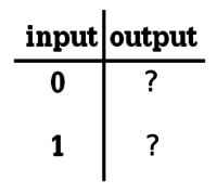
## Taking 0 (or close to zero) volts to be logic state "0" and 10 (or close to ten) volts to be logic state "1" construct the logic state truth table for this circuit (see right).[[File:Truth_table_inverter.png|thumb|200px|Truth table]] | |||
## What type of logic gate does the truth table indicate? | |||
Revision as of 20:05, 16 February 2015
Permanent Materials (located in the electronics area):

- power supplies
- function generators
- oscilloscopes
- Fluke 179 multimeter (MM)
- capacitance meter
- electronic proto-boards
- wire, resistors, capacitors, inductors, diodes, Op-Amps, other ICs
Materials to borrow when necessary
- LTSpice circuit simulation software (on computers in lab)
- lab copy of The Art of Electronics, Horowitz & Hill
- inductance meter
- Keithley voltage supply

Activities

- Read chapter 8 of Horowitz & Hill's The Art of Electronics.
- Read Chapters 10 and 11 of Keith Brindley's eBook Starting Electronics.
- Using T1 = TIP31C, R = 10k, R2 = 1k, Vcc = 10VDC construct the circuit shown at the right.
- Apply 0V to input A. What's the output Q?
- Apply 10V to input A. What's the output Q?
- Taking 0 (or close to zero) volts to be logic state "0" and 10 (or close to ten) volts to be logic state "1" construct the logic state truth table for this circuit (see right).

Truth table - What type of logic gate does the truth table indicate?