Optical Chaos with External Feedback Mirror: Difference between revisions
Aplstudent (talk | contribs) |
Aplstudent (talk | contribs) |
||
| (25 intermediate revisions by the same user not shown) | |||
| Line 21: | Line 21: | ||
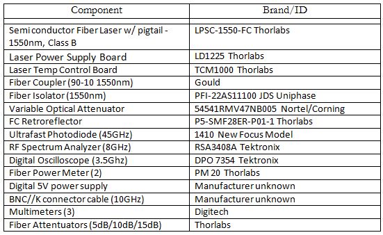
A List of Parts is here: [[File:Partslist.JPG]] | A List of Parts is here: [[File:Partslist.JPG]] | ||
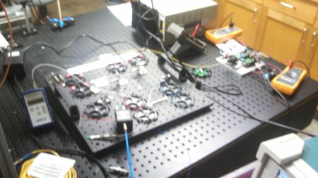
Picture of the setup: [[File:Setuplab.jpg|450px | Picture of the setup: [[File:Setuplab.jpg|450px]] | ||
== Goals == | == Goals == | ||
| Line 33: | Line 33: | ||
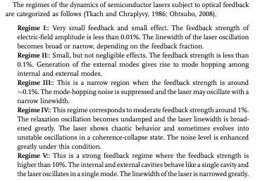
• Observe chaotic behavior in a few regions of instability | • Observe chaotic behavior in a few regions of instability | ||
[[File:Regimes.JPG|500px]] | |||
== Expected Results == | |||
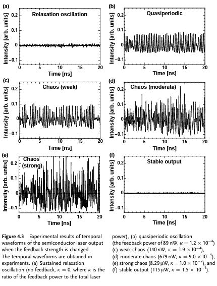
Time Series (on OSCILLOSCOPE) | |||
[[File:Expectedresults.JPG|450px|below]] | |||
Frequency Spectrum (on RF SPECTRUM ANALYZER) | |||
[[File:Frequencyresults.JPG|450px|below]] | |||
And, distinguishing between the Pattern of Chaos vs stochastic noise from the Sustained Relaxation Oscillation: | |||
[[File:NoiseVsChaos.JPG|450px]] | |||
== Results == | == Results == | ||
| Line 39: | Line 51: | ||
I decided to test my laser set-up in couple of different regimes: | I decided to test my laser set-up in couple of different regimes: | ||
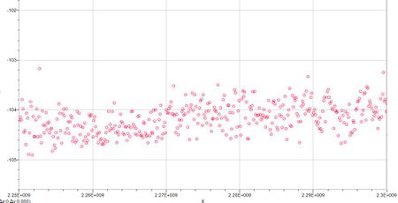
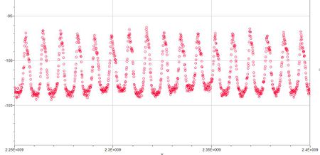
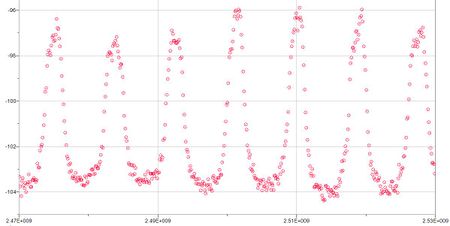
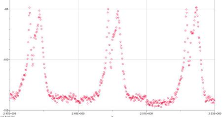
ON RF: sampled background signal, 100nW, 300nW, 500nW, 1uW, 5uW, 10 uW, 15uW, 20uW, 30uW, 40uW, 50uW, 55uW. Anything beyond this threatened the operable range of the VOA. Was able to sample at 317uW by cranking the input power and adding a 5dB fiber attentuator to the face of the PD | ON RF: sampled background signal, 100nW, 300nW, 500nW, 1uW, 5uW, 10 uW, 15uW, 20uW, 30uW, 40uW, 50uW, 55uW. Anything beyond this threatened the operable range of the VOA. Was able to sample at 317uW by cranking the input power and adding a 5dB fiber attentuator to the face of the PD. | ||
Units of the graph: | |||
X-axis is Frequency domain in Herz. (In the range of 2.25GHz - 2.4GHz) | |||
Y-axis is Power Output Level, measured in dBm. (In the range of -100dBm) | |||
background signal [[File:Background.JPG|450px]] | |||
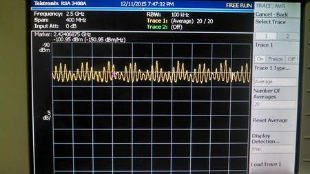
317uW w/ 5dB FA | 15uW [[File:15uw.JPG|450px]] | ||
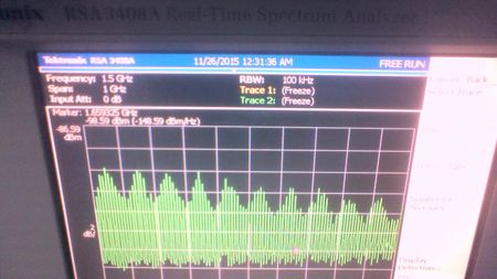
55uW [[File:55uw.JPG|450px]] | |||
317uW w/ 5dB FA [[File:317uw.JPG|450px]] | |||
This is what the data looks like on the scope. This is for a feedback level of 55uW, which was the highest that the VOA could run at, but still not enough to make strong chaos. | This is what the data looks like on the scope. This is for a feedback level of 55uW, which was the highest that the VOA could run at, but still not enough to make strong chaos. | ||
[[File:Modchaos.jpg|450px]] | |||
Unfortunately, there were some complicating issues that make me wonder if I actually achieved chaos. From the 15uW frequency plot, you can see peaks spaced 10MHz apart. This indicates a cavity, which matches the calculated external feedback frequency for it. | |||
[[File:Externalcavity.JPG]] | |||
From my estimated 10m length of laser fiber, FC, VOA and mirror, and using n~1.5 for the glass fiber, it predicts of a cavity of ~10MHz. | |||
But when you look at 55uW, there is no real difference in the plots. According to the theory, you should expect to see some route to quasiperiodicity (definite change in peak height), and then to chaos (sharp, even peaks). From the plotted results of 317uW, you CAN easily see the sharp tiny peaks of high chaos begin to form, as the power level drops. This is basically the effect of returning too much light into the laser cavity: instead of complicating things as it does at low feedback levels, it entirely wipes out the dynamics, and stabilizes the power. | |||
But what was evident to me towards the end of experiment was that there is no clear data for the mid-chaotic regime. This I think was caused by the creation of a cavity between the mirror and the worn APC face of the SL pigtail (about a meter shorter than the desired SL-mirror cavity). I base this on the fact that when I plugged the APC pigtail face through the 5m VOA and to the PD, I got an unwarranted external cavity with a frequency of 14MHz. This should not happen. | |||
So, in summary, if you look at the highest regime of feedback that I tested, you should see evidence of a cavity disappearing as the laser power increases. However, it is questionable if good chaotic feedback was attained in the lower dynamics, since the strong peaks seem to indicate a cavity that "locked" out these tiny signals. | |||
Finally, here is a picture of the first chaos that I achieved, at about 45uW. | |||
[[File:Chaos.jpeg|450px]] | |||
= Sources = | |||
[[File:Uchida.JPG|200px]] | |||
I highly recommend the use of the textbook "OPTICAL COMMUNICATION WITH CHAOTIC LASERS" by Atsushi Uchida (Wiley-VCH 2012). | |||
All the diagrams shown here were taken from the book. It can be accessed online with UO student access. (I found it by going to the UO Library site, searching for the title, which took me to ebrary.com, where it is available for download. Read it online, or offline with adobe digital editions reader. | |||
---- | |||
[[File:Ohtsube.jpg]] | |||
Also of assistance was "SEMICONDUCTOR LASERS: Stability, Instability and Chaos" by Junji Ohtsubo (Springer 2008). | |||
Latest revision as of 23:20, 14 December 2015
Background
Lasers have useful applications in our lives as clean, coherent light sources. However, lasers are not perfectly stable, and by feeding light back into the laser, one can create an unstable output. Manipulating the level of feedback, along with other variables, it has been shown that one can create “optical chaos”, or highly irregular and complex behavior in the power output. By nature, a chaotic system has an unpredictable output and is sensitive to slight changes in initial conditions. The output may at first seem random and disordered in strength, but it is really just complex behavior controlled by a deterministic rule (the Lang-Kobayashi equations).
Although it is difficult to find the usefulness of optical chaos in everyday life, with some ingenuity it has led to applications in optical communication security and random number generation. This experiment will only seek to prove that chaotic laser systems exist, and will not discuss synchronization in optical chaos (the idea that dual lasers can be "locked" in the same pattern") or verify any communication practically.
Setup
As you can imagine, there are several ways to feed light back into the laser cavity. (You may have even done so without noticing!). Here are a few configurations:
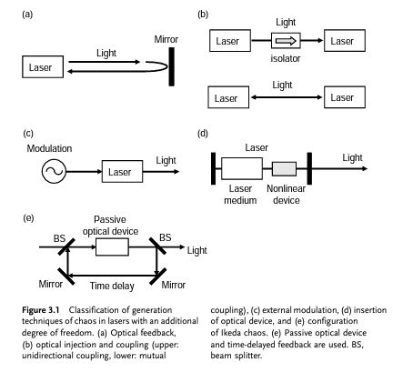
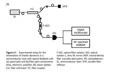
We will use Configuration A, directing laser light through a Fiber Coupler (a beamsplitter for a fiber), into a retroreflector (mirror), and returning it back to the source. This path has a Variable Optical Attenuator (VOA) on it, to control the amount of feedback power. Then, we can look at the chaotic light from the second path by measuring with an ultrafast Photodiode connected sometimes to an Oscilloscope and sometimes an RF Spectrum Analyzer. This second path has a Fiber Isolator (F-ISO) on it, to protect against unwanted back-reflection between the FC and the PD (we don't want it here, because we're still trying to measure the effect of the first cavity!).
A Diagram of the Setup is here:
Goals
Set-up a valid semiconductor laser (FC 1550nm class B) experiment to induce optical chaos.
• Prove the existence of optical chaos with experimental results
  • Get Power output on oscilloscope
  • RF spectra
• Observe chaotic behavior in a few regions of instability
Expected Results
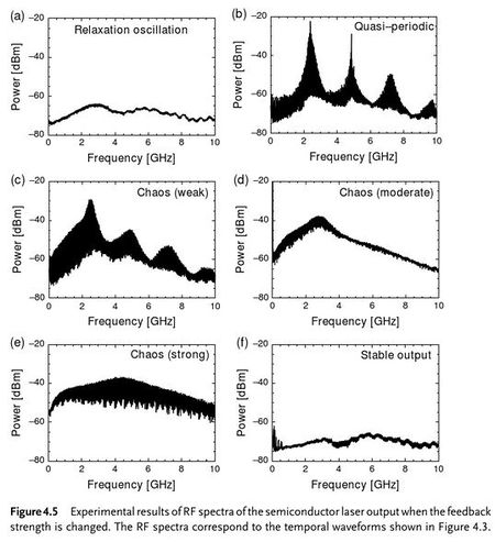
Frequency Spectrum (on RF SPECTRUM ANALYZER)
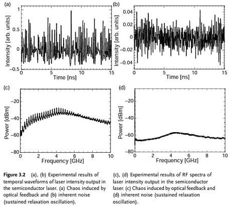
And, distinguishing between the Pattern of Chaos vs stochastic noise from the Sustained Relaxation Oscillation:
Results
I decided to test my laser set-up in couple of different regimes:
ON RF: sampled background signal, 100nW, 300nW, 500nW, 1uW, 5uW, 10 uW, 15uW, 20uW, 30uW, 40uW, 50uW, 55uW. Anything beyond this threatened the operable range of the VOA. Was able to sample at 317uW by cranking the input power and adding a 5dB fiber attentuator to the face of the PD.
Units of the graph:
X-axis is Frequency domain in Herz. (In the range of 2.25GHz - 2.4GHz) Y-axis is Power Output Level, measured in dBm. (In the range of -100dBm)
This is what the data looks like on the scope. This is for a feedback level of 55uW, which was the highest that the VOA could run at, but still not enough to make strong chaos.
Unfortunately, there were some complicating issues that make me wonder if I actually achieved chaos. From the 15uW frequency plot, you can see peaks spaced 10MHz apart. This indicates a cavity, which matches the calculated external feedback frequency for it.
From my estimated 10m length of laser fiber, FC, VOA and mirror, and using n~1.5 for the glass fiber, it predicts of a cavity of ~10MHz.
But when you look at 55uW, there is no real difference in the plots. According to the theory, you should expect to see some route to quasiperiodicity (definite change in peak height), and then to chaos (sharp, even peaks). From the plotted results of 317uW, you CAN easily see the sharp tiny peaks of high chaos begin to form, as the power level drops. This is basically the effect of returning too much light into the laser cavity: instead of complicating things as it does at low feedback levels, it entirely wipes out the dynamics, and stabilizes the power.
But what was evident to me towards the end of experiment was that there is no clear data for the mid-chaotic regime. This I think was caused by the creation of a cavity between the mirror and the worn APC face of the SL pigtail (about a meter shorter than the desired SL-mirror cavity). I base this on the fact that when I plugged the APC pigtail face through the 5m VOA and to the PD, I got an unwarranted external cavity with a frequency of 14MHz. This should not happen.
So, in summary, if you look at the highest regime of feedback that I tested, you should see evidence of a cavity disappearing as the laser power increases. However, it is questionable if good chaotic feedback was attained in the lower dynamics, since the strong peaks seem to indicate a cavity that "locked" out these tiny signals.
Finally, here is a picture of the first chaos that I achieved, at about 45uW.
Sources
I highly recommend the use of the textbook "OPTICAL COMMUNICATION WITH CHAOTIC LASERS" by Atsushi Uchida (Wiley-VCH 2012). All the diagrams shown here were taken from the book. It can be accessed online with UO student access. (I found it by going to the UO Library site, searching for the title, which took me to ebrary.com, where it is available for download. Read it online, or offline with adobe digital editions reader.
Also of assistance was "SEMICONDUCTOR LASERS: Stability, Instability and Chaos" by Junji Ohtsubo (Springer 2008).
