Sonoluminescence: Difference between revisions
No edit summary |
No edit summary |
||
| (8 intermediate revisions by 2 users not shown) | |||
| Line 1: | Line 1: | ||
== Sonoluminescence == | |||
[http://hank.uoregon.edu/experiments/sonoluminescence/sonoluminescence-home.html Sono Web Page] | |||
What we are trying to accomplish in the Sonoluminescence Project is to create a Single-Bubble Sonoluminescence (SBSL). Sonoluminescence is where bubbles that were formed by high | What we are trying to accomplish in the Sonoluminescence Project is to create a Single-Bubble Sonoluminescence (SBSL). Sonoluminescence is where bubbles that were formed by high | ||
frequency standing waves collapse and produce light. The center of the bubble is predicted by some to be as high as 1,000,000K but recent results show it at only 10-20 thousand Kelvin [http://www.annualreviews.org/doi/abs/10.1146/annurev.physchem.59.032607.093739]. Sonoluminescence is hoping to be a way to produce fusion and the center of a bubble is a weak plasma [http://www.nature.com/news/2005/050228/full/news050228-7.html]. The mechanisms of sonoluminescence are somewhat unknown to the scientific community. There are quite a few theories, at least 9 current theories as ‘Sonoluminescence’ (F. Ronald Young, CRC Press) lists them. One of the current competing theories is Bremsstrahlung radiation, this theory states that an electron passing through an electric field (of a polarized atom, neutral atom or plasma) can either emit a photon without losing all of its kinetic energy and remain free or it can absorb a photon and acquire additional kinetic energy. Essentially it can give off light or wait, absorb more photons and give off light at a later time. Bremsstrahlung doesn't predict the entire energy spectrum perfectly though, a sonoluminescence flash gives off more light in the UV spectrum than Bremsstrahlung predicts. | frequency standing waves collapse and produce light. The center of the bubble is predicted by some to be as high as 1,000,000K but recent results show it at only 10-20 thousand Kelvin [http://www.annualreviews.org/doi/abs/10.1146/annurev.physchem.59.032607.093739]. Sonoluminescence is hoping to be a way to produce fusion and the center of a bubble is a weak plasma [http://www.nature.com/news/2005/050228/full/news050228-7.html]. The mechanisms of sonoluminescence are somewhat unknown to the scientific community. There are quite a few theories, at least 9 current theories as ‘Sonoluminescence’ (F. Ronald Young, CRC Press) lists them. One of the current competing theories is Bremsstrahlung radiation, this theory states that an electron passing through an electric field (of a polarized atom, neutral atom or plasma) can either emit a photon without losing all of its kinetic energy and remain free or it can absorb a photon and acquire additional kinetic energy. Essentially it can give off light or wait, absorb more photons and give off light at a later time. Bremsstrahlung doesn't predict the entire energy spectrum perfectly though, a sonoluminescence flash gives off more light in the UV spectrum than Bremsstrahlung predicts. | ||
| Line 8: | Line 12: | ||
We used a Rigol DG 1022 function generator and a Rigol DS 1102 oscilloscope throughout the project. It is best to take some time to get familiar with this equipment. Knowing how to scan, zoom and trigger a signal properly is important when analyzing the signal from the flask. | We used a Rigol DG 1022 function generator and a Rigol DS 1102 oscilloscope throughout the project. It is best to take some time to get familiar with this equipment. Knowing how to scan, zoom and trigger a signal properly is important when analyzing the signal from the flask. | ||
The amp circuit consists of an operational amplifier and a push pull transistor pair (commonly known as a Class B push pull output). The op amp is needed to increase the voltage because the maximum voltage from the function generator is 20 Vpp. | The amp circuit consists of an operational amplifier and a push pull transistor pair (commonly known as a Class B push pull output). The op amp is needed to increase the voltage because the maximum voltage from the function generator is 20 Vpp. We use a CA 314 with an inverted 1.5 gain using a 15k ohm (R2) and a 10k ohm resistors (R1). The gain can be calculated using the ratio of the two resistors R2/R1. We should note that the op amp configuration is that of an inverting op amp, but for some reason, the voltage does not actually invert. Regardless, the voltage gain is achieved. It is important to check that the op amp is working properly, so test each prong and make sure you get the expected voltages. | ||
The next part of the amp circuit is the push pull pair which increases the current. A TIP 31C NPN and a TIP 32C PNP were used. To test that the amp circuit, you need to place a load resistor ( a 10 ohm will do), in series with a meter for impedance. | The next part of the amp circuit is the push pull pair which increases the current. A TIP 31C NPN and a TIP 32C PNP were used. To test that the amp circuit, you need to place a load resistor ( a 10 ohm will do), in series with a meter for impedance. | ||
[[File: | [[File:circuitboard.jpg]] | ||
('''''A:''''' function generator input '''''B:''''' 10k ohm resistor '''''C:''''' 15k ohm resistor '''''D:''''' CA 314 op amp '''''E:''''' ''top:'' TIP 31 C NPN ''bottom:'' TIP 32 C PNP '''''F:''''' output to tunable inductor) | |||
| Line 23: | Line 25: | ||
Connect the inductor to the PZT's on the flask. In our lab, we used a 100 ml quartz spherical flask. To test the voltage across the PZT's, find a voltage probe and connect it to the oscilloscope. With the function generator outputting a frequency of 20-25 kHz (may vary depending on the size and shape of the flask being used), tune the inductor until maximum amplitude. The voltage across the PZT's should be around several hundred Vpp. | Connect the inductor to the PZT's on the flask. In our lab, we used a 100 ml quartz spherical flask. To test the voltage across the PZT's, find a voltage probe and connect it to the oscilloscope. With the function generator outputting a frequency of 20-25 kHz (may vary depending on the size and shape of the flask being used), tune the inductor until maximum amplitude. The voltage across the PZT's should be around several hundred Vpp. | ||
NOTE: The flask is broken and a new flask with attached PZT's needs to be brought in. | |||
''( | [[File:Sono_inductor.JPG|350px|left]][[File:Sono_flask.JPG|350px|center]] | ||
''('''Left''': Tunable inductor '''Right''': Flask with two PZT's. Microphone not shown, this is not the flask we used. This flask is just normal glass, we used a special fused Quartz flask) | |||
'' | '' | ||
| Line 41: | Line 44: | ||
[https://docs.google.com/presentation/d/1qnqJ1O6VjH-6Gj-73UQDFmeswQyS3Bc5fzNeV5CowM0/edit#slide=id.p Fall_2013] | [https://docs.google.com/presentation/d/1qnqJ1O6VjH-6Gj-73UQDFmeswQyS3Bc5fzNeV5CowM0/edit#slide=id.p Fall_2013] | ||
[[Fall 2013]] | |||
[[The Construction and Testing of Various Sonoluminescence Vessels]] | |||
Latest revision as of 21:49, 8 January 2025
Sonoluminescence
What we are trying to accomplish in the Sonoluminescence Project is to create a Single-Bubble Sonoluminescence (SBSL). Sonoluminescence is where bubbles that were formed by high frequency standing waves collapse and produce light. The center of the bubble is predicted by some to be as high as 1,000,000K but recent results show it at only 10-20 thousand Kelvin [1]. Sonoluminescence is hoping to be a way to produce fusion and the center of a bubble is a weak plasma [2]. The mechanisms of sonoluminescence are somewhat unknown to the scientific community. There are quite a few theories, at least 9 current theories as ‘Sonoluminescence’ (F. Ronald Young, CRC Press) lists them. One of the current competing theories is Bremsstrahlung radiation, this theory states that an electron passing through an electric field (of a polarized atom, neutral atom or plasma) can either emit a photon without losing all of its kinetic energy and remain free or it can absorb a photon and acquire additional kinetic energy. Essentially it can give off light or wait, absorb more photons and give off light at a later time. Bremsstrahlung doesn't predict the entire energy spectrum perfectly though, a sonoluminescence flash gives off more light in the UV spectrum than Bremsstrahlung predicts.
Our goal was to collect as much light possible from the bubble for analysis. In order to do this, the bubble needs to be stable enough to emit a sufficient amount of light.
Our first step is to create a bubble. The basic set-up of our project is: Function Generator -> Amp Circuit -> Tunable Inductor -> Flask -> Oscilloscope.
We used a Rigol DG 1022 function generator and a Rigol DS 1102 oscilloscope throughout the project. It is best to take some time to get familiar with this equipment. Knowing how to scan, zoom and trigger a signal properly is important when analyzing the signal from the flask.
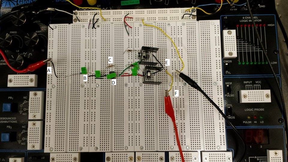
The amp circuit consists of an operational amplifier and a push pull transistor pair (commonly known as a Class B push pull output). The op amp is needed to increase the voltage because the maximum voltage from the function generator is 20 Vpp. We use a CA 314 with an inverted 1.5 gain using a 15k ohm (R2) and a 10k ohm resistors (R1). The gain can be calculated using the ratio of the two resistors R2/R1. We should note that the op amp configuration is that of an inverting op amp, but for some reason, the voltage does not actually invert. Regardless, the voltage gain is achieved. It is important to check that the op amp is working properly, so test each prong and make sure you get the expected voltages.
The next part of the amp circuit is the push pull pair which increases the current. A TIP 31C NPN and a TIP 32C PNP were used. To test that the amp circuit, you need to place a load resistor ( a 10 ohm will do), in series with a meter for impedance.
(A: function generator input B: 10k ohm resistor C: 15k ohm resistor D: CA 314 op amp E: top: TIP 31 C NPN bottom: TIP 32 C PNP F: output to tunable inductor)
When everything in the amp circuit is in place, the load resistor can be taken out and the tunable inductor can be connected to the output.
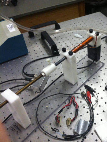
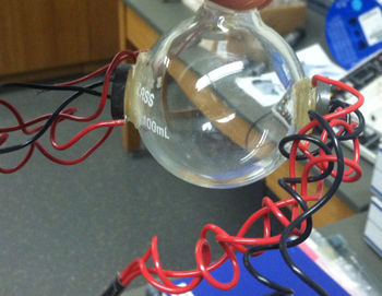
Connect the inductor to the PZT's on the flask. In our lab, we used a 100 ml quartz spherical flask. To test the voltage across the PZT's, find a voltage probe and connect it to the oscilloscope. With the function generator outputting a frequency of 20-25 kHz (may vary depending on the size and shape of the flask being used), tune the inductor until maximum amplitude. The voltage across the PZT's should be around several hundred Vpp.
NOTE: The flask is broken and a new flask with attached PZT's needs to be brought in.


(Left: Tunable inductor Right: Flask with two PZT's. Microphone not shown, this is not the flask we used. This flask is just normal glass, we used a special fused Quartz flask)
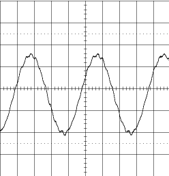
Now with everything in place, connect the microphone at the bottom of the flask to the oscilloscope. Water is degassed by boiling distilled water for 15 minutes and then poured into the flask. We first located the resonant frequency and then adjusted the driving voltage to maximum amplitude. To create an bubble, an eye dropper was used. If a bubble was successfully trapped, distortions of the acoustic signal can be seen at the peaks.
 (This is an example of a trapped bubble taken from www.techmind.org)
The next step for this project would be to set up a vacuum pump to speed up water preparation and to construct a resonating feedback circuit that will able to track the resonating frequency of the flask to increase the stability of the bubble.
Presentation:
The Construction and Testing of Various Sonoluminescence Vessels
